


När vi rör på vår hand så ska handen göra samma rörelse.
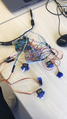
vi har fått handen att funka och den är trådlöst.


——————- 2018 handen transmitter with flex sensors —————–
/* YourDuinoStarter Example: nRF24L01 Radio Remote control: Joystick to Servos
  - WHAT IT DOES
   Joystick on this Arduino communicates by nRF25L01 Radio to
   a second Arduino with an nRF24L01 radio and 2 pan-tilt servos
   SEE: The variable 'hasHardware'. You can test without Joystick and later set hasHardware = true;

  - SEE the comments after "//" on each line below
  - CONNECTIONS:
   - nRF24L01 Radio Module: See http://arduino-info.wikispaces.com/Nrf24L01-2.4GHz-HowTo
   1 - GND
   2 - VCC 3.3V !!! NOT 5V
   3 - CE to Arduino pin 7
   4 - CSN to Arduino pin 8
   5 - SCK to Arduino pin 13
   6 - MOSI to Arduino pin 11
   7 - MISO to Arduino pin 12
   8 - UNUSED
  - V2.12 02/08/2016
   - Uses the RF24 Library by TMRH20 and Maniacbug: https://github.com/TMRh20/RF24 (Download ZIP)
   Questions: terry@yourduino.com */

/*-----( Import needed libraries )-----*/
#include <SPI.h>   // Comes with Arduino IDE
#include "RF24.h"  // Download and Install (See above)
#include "printf.h" // Needed for "printDetails" Takes up some memory
/*-----( Declare Constants and Pin Numbers )-----*/
#define  CE_PIN  7   // The pins to be used for CE and SN
#define  CSN_PIN 8

#define pekfinger A1  // The Joystick potentiometers connected to Arduino Analog inputs
#define mittenfinger A2
#define ringfinger A3  // The Joystick push-down switch, will be used as a Digital input
#define lillfinger A4

/*-----( Declare objects )-----*/
/* Hardware configuration: Set up nRF24L01 radio on SPI bus plus (usually) pins 7 & 8 (Can be changed) */
RF24 radio(CE_PIN, CSN_PIN);

/*-----( Declare Variables )-----*/
byte addresses[][6] = {"1Node", "2Node"}; // These will be the names of the "Pipes"

unsigned long timeNow;  // Used to grab the current time, calculate delays
unsigned long started_waiting_at;
boolean timeout;       // Timeout? True or False

// Allows testing of radios and code without Joystick hardware. Set 'true' when joystick connected
//boolean hasHardware = false;
boolean hasHardware = true;

/**
  Create a data structure for transmitting and receiving data
  This allows many variables to be easily sent and received in a single transmission
  See http://www.cplusplus.com/doc/tutorial/structures/
*/
struct dataStruct {
  unsigned long _micros;  // to save response times
  int flexValue1;          // The Joystick position values
  int flexValue2;
  int flexValue3;
  int flexValue4;
} myData;                 // This can be accessed in the form:  myData.Xposition  etc.


void setup()   /****** SETUP: RUNS ONCE ******/
{
  Serial.begin(115200);  // MUST reset the Serial Monitor to 115200 (lower right of window )
  // NOTE: The "F" in the print statements means "unchangable data; save in Flash Memory to conserve SRAM"
  Serial.println(F("YourDuino.com Example: Send joystick data by nRF24L01 radio to another Arduino"));
  printf_begin(); // Needed for "printDetails" Takes up some memory
  //pinMode(JOYSTICK_SW, INPUT_PULLUP);  // Pin A2 will be used as a digital input

  radio.begin();          // Initialize the nRF24L01 Radio
  radio.setChannel(108);  // Above most WiFi frequencies
  radio.setDataRate(RF24_250KBPS); // Fast enough.. Better range

  // Set the Power Amplifier Level low to prevent power supply related issues since this is a
  // getting_started sketch, and the likelihood of close proximity of the devices. RF24_PA_MAX is default.
  // PALevelcan be one of four levels: RF24_PA_MIN, RF24_PA_LOW, RF24_PA_HIGH and RF24_PA_MAX
  radio.setPALevel(RF24_PA_LOW);
  //  radio.setPALevel(RF24_PA_MAX);

  // Open a writing and reading pipe on each radio, with opposite addresses
  radio.openWritingPipe(addresses[0]);
  radio.openReadingPipe(1, addresses[1]);

  // Start the radio listening for data
  radio.startListening();

//  radio.printDetails(); //Uncomment to show LOTS of debugging information
}//--(end setup )---


void loop()   /****** LOOP: RUNS CONSTANTLY ******/
{
  radio.stopListening();                                    // First, stop listening so we can talk.

  if (hasHardware)  // Set in variables at top
  {
    /*********************( Read the Joystick positions )*************************/
    myData.flexValue1 = analogRead(A1);
    myData.flexValue2 = analogRead(A2);
    myData.flexValue3 = analogRead(A3);
    myData.flexValue4 = analogRead(A4);
  }
  else
  {
    myData.flexValue1 = 100;  // Send some known fake data
    myData.flexValue2 = 100;
    myData.flexValue3 = 100;
    myData.flexValue4 = 100;
  }

  myData._micros = micros();  // Send back for timing


  Serial.print(F("Now sending  -  "));

  if (!radio.write( &myData, sizeof(myData) )) {            // Send data, checking for error ("!" means NOT)
    Serial.println(F("Transmit failed "));
  }

  radio.startListening();                                    // Now, continue listening

  started_waiting_at = micros();               // timeout period, get the current microseconds
  timeout = false;                            //  variable to indicate if a response was received or not

  while ( ! radio.available() ) {                            // While nothing is received
    if (micros() - started_waiting_at > 200000 ) {           // If waited longer than 200ms, indicate timeout and exit while loop
      timeout = true;
      break;
    }
  }

  if ( timeout )
  { // Describe the results
    Serial.println(F("Response timed out -  no Acknowledge."));
  }
  else
  {
    // Grab the response, compare, and send to Serial Monitor
    radio.read( &myData, sizeof(myData) );
    timeNow = micros();

    // Show it
    Serial.print(F("Sent "));
    Serial.print(timeNow);
    Serial.print(F(", Got response "));
    Serial.print(myData._micros);
    Serial.print(F(", Round-trip delay "));
    Serial.print(timeNow - myData._micros);
    Serial.println(F(" microseconds "));

  }

  // Send again after delay. When working OK, change to something like 100
  delay(100);

}//--(end main loop )---

/*-----( Declare User-written Functions )-----*/

// NONE YET
//*********( THE END )***********
————2018 Handen Receiver with servos ——
/* YourDuinoStarter Example: nRF24L01 Radio remote control of servos by joystick
  - WHAT IT DOES
   Joystick on other Arduino communicates by nRF25L01 Radio to
   this Arduino with 2 pan-tilt servos
   SEE: The variable 'hasHardware'. You can test without servos and later set hasHardware = true;
        You NEED separate Servo power, not USB. YourDuino RoboRED has built in 2A power for servos
  - SEE the comments after "//" on each line below
  - CONNECTIONS:
   - nRF24L01 Radio Module: See http://arduino-info.wikispaces.com/Nrf24L01-2.4GHz-HowTo
   1 - GND
   2 - VCC 3.3V !!! NOT 5V
   3 - CE to Arduino pin 7
   4 - CSN to Arduino pin 8
   5 - SCK to Arduino pin 13
   6 - MOSI to Arduino pin 11
   7 - MISO to Arduino pin 12
   8 - UNUSED

  - V2.12 02/08/2016
   - Uses the RF24 Library by TMRH20 and Maniacbug: https://github.com/TMRh20/RF24 (Download ZIP)
   Questions: terry@yourduino.com */

/*-----( Import needed libraries )-----*/
#include <SPI.h>   // Comes with Arduino IDE
#include "RF24.h"  // Download and Install (See above)
#include "printf.h" // Needed for "printDetails" Takes up some memory
// NEED the SoftwareServo library installed
// http://playground.arduino.cc/uploads/ComponentLib/SoftwareServo.zip
#include <SoftwareServo.h>  // Regular Servo library creates timer conflict!
/*-----( Declare Constants and Pin Numbers )-----*/
#define  CE_PIN  7   // The pins to be used for CE and SN
#define  CSN_PIN 8

//#define ServoHorizontalPIN 3   //Pin Numbers for servos and laser/LED
//#define ServoVerticalPIN   5
//#define LaserPIN           6

#define ServoMIN_H  10  // Don't go to very end of servo travel
#define ServoMAX_H  170 // which may not be all the way from 0 to 180.
#define ServoMIN_V  10  // Don't go to very end of servo travel
#define ServoMAX_V  170 // which may not be all the way from 0 to 180

/*-----( Declare objects )-----*/
/* Hardware configuration: Set up nRF24L01 radio on SPI bus plus (usually) pins 7 & 8 (Can be changed) */
RF24 radio(CE_PIN, CSN_PIN);

SoftwareServo pekServo;
SoftwareServo mittenServo;
SoftwareServo ringServo;
SoftwareServo lillServo;

/*-----( Declare Variables )-----*/
byte addresses[][6] = {"1Node", "2Node"}; // These will be the names of the "Pipes"

// Allows testing of radios and code without servo hardware. Set 'true' when servos connected
//boolean hasHardware = false;  // Allows testing of radios and code without Joystick hardware.
boolean hasHardware = true;

int flexValue1Received; // Variable to store received Joystick values
int flexValue2Received;
int flexValue3Received;
int flexValue4Received;

int pekServoPosition;    // variable to store the servo position
int mittenServoPosition;
int ringServoPosition;
int lillServoPosition;

/**
  Create a data structure for transmitting and receiving data
  This allows many variables to be easily sent and received in a single transmission
  See http://www.cplusplus.com/doc/tutorial/structures/
*/
struct dataStruct {
  unsigned long _micros;  // to save response times
  int flexValue1;          // The Joystick position values
  int flexValue2;
  int flexValue3;
  int flexValue4;
} myData;                 // This can be accessed in the form:  myData.Xposition  etc.


void setup()   /****** SETUP: RUNS ONCE ******/
{
  Serial.begin(115200);   // MUST reset the Serial Monitor to 115200 (lower right of window )
  // NOTE: The "F" in the print statements means "unchangable data; save in Flash Memory to conserve SRAM"
  Serial.println(F("YourDuino.com Example: Receive joystick data by nRF24L01 radio from another Arduino"));
  Serial.println(F("and control servos if attached (Check 'hasHardware' variable"));
  printf_begin(); // Needed for "printDetails" Takes up some memory
  /*-----( Set up servos )-----*/
  if (hasHardware)
  {
    pekServo.attach(5);  // attaches the servo to the servo object
    mittenServo.attach(3);
    ringServo.attach(10);
    lillServo.attach(9);
  }

  radio.begin();          // Initialize the nRF24L01 Radio
  radio.setChannel(108);  // 2.508 Ghz - Above most Wifi Channels
  radio.setDataRate(RF24_250KBPS); // Fast enough.. Better range

  // Set the Power Amplifier Level low to prevent power supply related issues since this is a
  // getting_started sketch, and the likelihood of close proximity of the devices. RF24_PA_MAX is default.
  // PALevelcan be one of four levels: RF24_PA_MIN, RF24_PA_LOW, RF24_PA_HIGH and RF24_PA_MAX
  radio.setPALevel(RF24_PA_LOW);
  //   radio.setPALevel(RF24_PA_MAX);

  // Open a writing and reading pipe on each radio, with opposite addresses
  radio.openWritingPipe(addresses[1]);
  radio.openReadingPipe(1, addresses[0]);

  // Start the radio listening for data
  radio.startListening();
//  radio.printDetails(); //Uncomment to show LOTS of debugging information
}//--(end setup )---


void loop()   /****** LOOP: RUNS CONSTANTLY ******/
{

  if ( radio.available())
  {

    while (radio.available())   // While there is data ready to be retrieved from the receive pipe
    {
      radio.read( &myData, sizeof(myData) );             // Get the data
    }

    radio.stopListening();                               // First, stop listening so we can transmit
    radio.write( &myData, sizeof(myData) );              // Send the received data back.
    radio.startListening();                              // Now, resume listening so we catch the next packets.

    Serial.print(F("Packet Received - Sent response "));  // Print the received packet data
    Serial.print(myData._micros);
    Serial.print(F("uS flex1 = "));
    Serial.print(myData.flexValue1);
    Serial.print(F(" flex2 = "));
    Serial.print(myData.flexValue2);
    Serial.print(F(" flex3 = "));
    Serial.print(myData.flexValue3);
    Serial.print(F(" flex4 = "));
    Serial.println(myData.flexValue4);


  } // END radio available

  if (hasHardware)
  {
    /*-----( Calculate servo position values, send to the servos )-----*/
    SoftwareServo::refresh();//refreshes servo to keep them updating
    flexValue1Received  = myData.flexValue1;  // Get the values received
    flexValue2Received  = myData.flexValue2;
    flexValue3Received  = myData.flexValue3;
    flexValue4Received  = myData.flexValue4;

    // scale it to use it with the servo (value between MIN and MAX)
    pekServoPosition  = map(flexValue1Received, 587, 300, ServoMIN_H , ServoMAX_H);
    mittenServoPosition  = map(flexValue2Received, 580, 380, ServoMIN_H , ServoMAX_H);
    ringServoPosition  = map(flexValue3Received, 560, 430, ServoMIN_H , ServoMAX_H);
    lillServoPosition  = map(flexValue4Received, 600, 460, ServoMIN_H , ServoMAX_H);


    // tell servos to go to position
    pekServo.write(pekServoPosition);
    mittenServo.write(mittenServoPosition);
    ringServo.write(ringServoPosition);
    lillServo.write(lillServoPosition);
  } // END hasHardware
}//--(end main loop )---

/*-----( Declare User-written Functions )-----*/

// NONE YET
//*********( THE END )***********
————
